LaserDriver - A6211, Thermistor / Modulation
This is an enhancement of the smaller A6211 laser diode driver. This board protects the laser diode from over-temperature and it can accept a PWM modulation to control the current through the diode.
1. Technical Data
- Supply voltage VIN: 7V – 48V DC
- Laser diode voltage VLD: 1.8V – 46V (VLD ≤ VIN - 2V)
- Laser diode current ILD: ILD ≤ 2.5A • Modulation: TTL (VTTL ≤ VIN – 1V), 5V/3.3V/2.5V or constant current
- Dimensions: 17.7mm x 28.3mm
- Thermal protection by means of an NTC thermistor or an active temperature sensor
2. Description
The board is a compact laser diode or LED driver capable of handling up to 2.5A of current through the diode. By means of the onboard trimmer RV1, the current is set to a user-defined value within a predefined range (e.g. 1A – 2.5A). The exact range depends on the factory board configuration.
The board supports external TTL modulation. The modulation voltage level should be greater than 1.8V and less than or equal to VIN – 1V.
An additional feature is the thermal protection by means of an NTC thermistor (10K to 33K depending on the factory board configuration). The temperature value TSHUTDOWN at which the thermal protection is activated is set by means of the onboard trimmer RV2 (e.g. 42°C to 100°C). The exact range depends on the factory board configuration.
3. Board configurations – TTL modulation and thermal protection support
Regarding TTL modulation and thermal protection support, there are two possible factory configurations of the board:
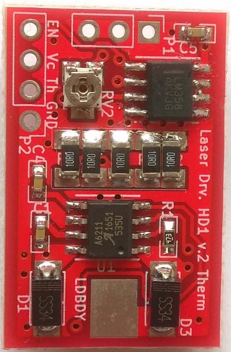
- Configuration A supports thermal protection by means of an NTC thermistor or an active temperature sensor and is recognized by the presence of the 8-pin integrated circuit U2 next to connector P1. This configuration may be tweaked to support TTL modulation but this has to be done on a case by case basis.
- Configuration B does not support thermal protection and is recognized by the absence of the 8-pin integrated circuit U2 next to connector P1. This configuration is used when TTL modulation is needed.
4. Setting up the board
The laser diode or LED should be reliably connected to the board before the power supply is switched on. If the diode is connected to the board after the power supply has been switched on or if its connection to the board is disrupted during operation, the diode may be damaged.
Trimmers for board adjustments:
- RV1 trimmer – adjustment of ILD,
- RV2 trimmer – adjustment of TSHUTDOWN.
Board Connectors:
- P1 – three ground pins (GND),
- P2 – control pins
- EN pin – for TTL modulation control (configuration B) or status readout (configuration A),
- Vc pin – power supply after the protection diode D3. Used for powering active temperature sensors,
- Th pin – for thermistor connection,
- GND pin – ground pin,
- LDBDY – pad for connection of the positive power supply input,
- LDA – two pads for connection of the diode, the anode pad is the pad closest to the LDA marking, the other pad is the cathode pad.
The negative power supply input is connected to one of the four ground pins (the three pins of connector P1 or the GND pin of connector P2). The positive power supply input is connected to the LDBDY pad.
For thermal protection (board configuration A), either an NTC thermistor or an active temperature sensor may be used. A thermistor is connected to the Th pin of connector P2 and one of the ground pins (no polarity). An active temperature sensor is connected to the Vc pin and a ground pin – as power supplies – and its output is connected to the Th pin.
If no thermal protection and no modulation are used, depending on the board configuration, the Th pin (configuration A) or the EN pin (configuration B) should be connected to Vc to enable the laser driver at all times.
5. Connection to a Raspberry Pi 3, model B
The laser driver board can be connected to a Raspberry Pi board, so that the Raspberry Pi can switch on or off the laser diode or LED.
Generally, only configuration B of the board should be used for connection to a Raspberry Pi. It may be possible to also use configuration A, but you need to modify the board accordingly.
The connection to the Raspberry Pi should be done in the following way:
Step 1. Ensure that the grounds of the laser driver board and the Raspberry Pi board are connected.
The preferred way to do this is to connect the grounds of their power supplies together as close to the power supplies as possible and run separate ground wires for the Raspberry Pi and the laser driver board (star ground configuration).
If this is not possible, then do the connection at the boards – connect a ground pin of the laser driver board to a ground pin of the Raspberry Pi. For the laser driver board, the ground pins are the three pins of connector P1 and the GND pin of connector P2. For Raspberry Pi, the ground pins of the GPIO connector J8 are listed in black in the table below (pin 1 is the pin closest to the marking J8 in the picture below).
Step 2. Depending on the board configuration, connect the EN pin (configuration B) or the Th pin (configuration A) of connector P2 of the laser driver board to a GPIO pin of the GPIO connector J8 of the Raspberry Pi.
The board is designed for hand soldering. If you wish to know more about it, please drop me a note using the about page.
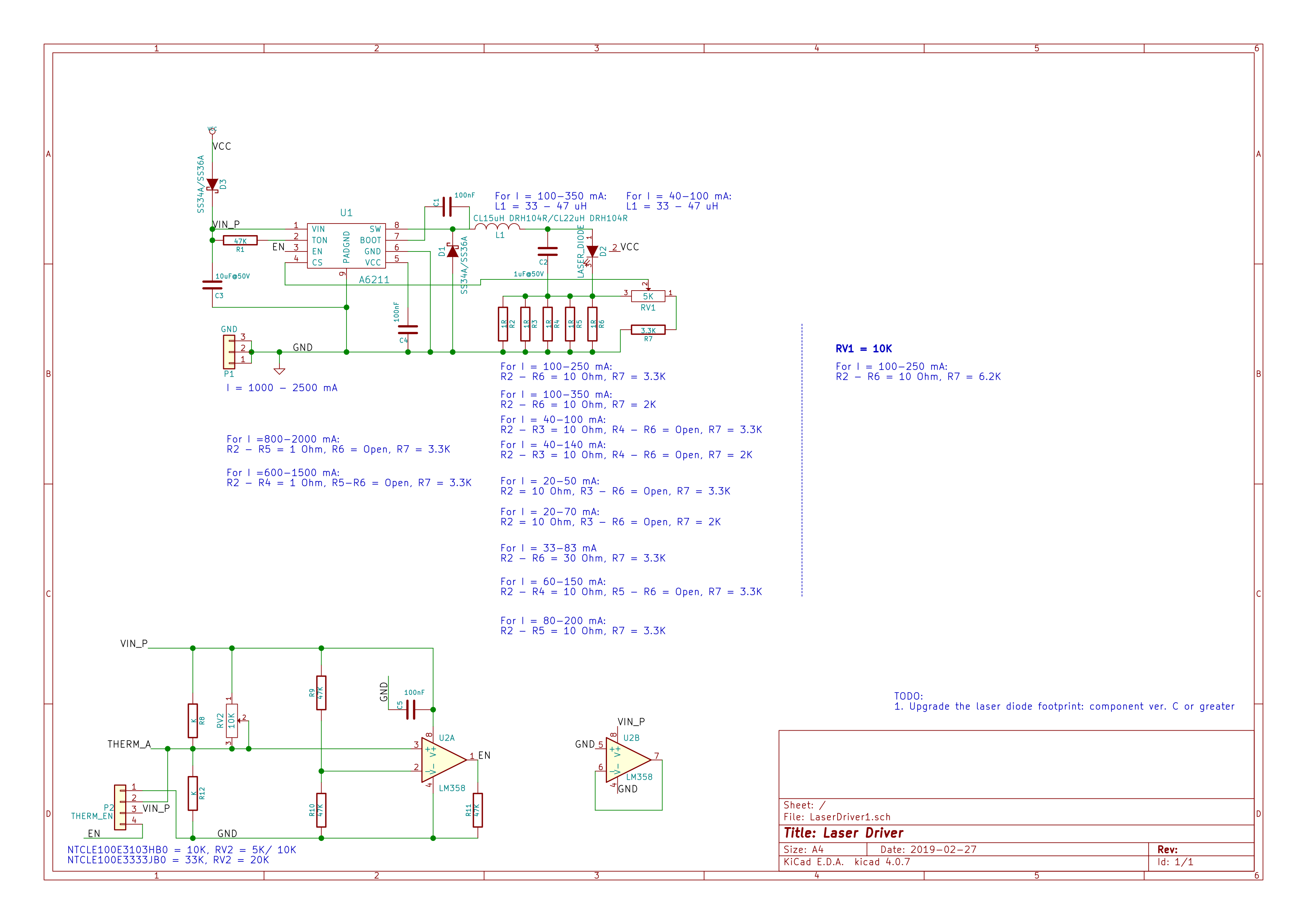
Schematics: