Laser and TEC Driver - 5A
1. Technical Data
Laser Driver
-
Supply voltage: 5V – 28V DC
-
Laser diode voltage: 1.8V – 25V
-
Laser diode current: up to 5A
-
Modulation: analog or TTL 5V/3.3V/2.5V/1.8V, constant current
-
Modulation frequency: up to 500KHz
TEC Driver
-
Supply voltage: 5V – 28V DC
-
TEC voltage: 1.8V – 25V
-
TEC current: up to 5A
- Control: via microcontroller Atmel ATmega328P compatible with Arduino Pro/Mini.
2. Description
The board combines a laser driver and a TEC driver. It works with a DC power supply in the range from 5V to 28V, which allows it to control several laser diodes in series for more optical power. The laser driver and the TEC driver are designed as two independent sections of the board – if needed the board can be physically cut in the middle in order to separate the sections and reduce the physical dimensions.
The laser driver section provides a current of up to 5A through an integrated DC-DC converter. The maximum value of the current and thus the maximum intensity of the laser diode is set by two on-board trimmers. The actual current through the laser diode at each point in time is controlled via a modulation input supporting analog and TTL modulation of up to 5V. The maximum modulation frequency is about 500Khz. If there is no modulation source, the board can also work in constant current mode. The working voltage of the laser diode is set via an on-board trimmer and ranges from 1.8V up to 25V depending on the power supply. There is also an opto-isolated input for enabling the laser diodes or shutting them down in emergency situations (e.g. overheating).
The TEC driver section controls one TEC (Peltier) element. It uses up to two temperature sensors (thermistors or active sensors) to measure the laser diode temperature. The ATmega328P microcontroller uses the measured values to drive the TEC element in an optimum way. The TEC driver has 4 on-board trimmers for setting parameters, e. g. the target laser diode temperature or the maximum TEC voltage and current. The microcontroller is designed to be compatible with the popular Arduino Pro/Mini platform and it also supports digital-IO, UART, SPI or I2C communications to and from external boards. It can be programmed by the user to change the TEC control algorithm or to do other tasks. Through the I2C headers of the board, an OLED or an LCD display can be connected to show relevant data – temperatures, TEC control status, etc.
The board has the following protections built-in: two fuses, ESD protection, reverse-polarity protection, short-circuit protection and over-temperature protection.
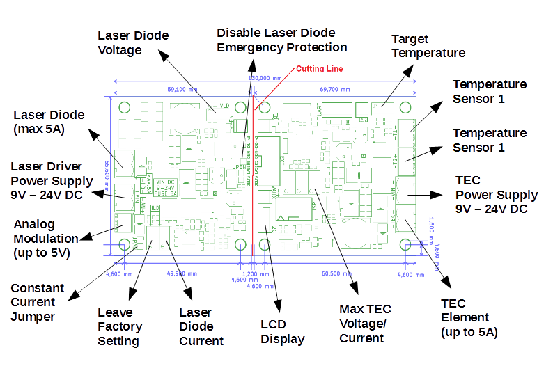
3. Setting up the board
Laser Driver
-
JPAN jumper – set to enable constant current mode without modulation, remove when using analog modulation.
-
ILD trimmers – used to set the maximum current through the laser diode. Generally, do not change the default setting of the trimmer directly next to the JPAN jumper.
-
VLD trimmer – used to set the working voltage of the laser diode. It should be set to a value of about one to two volts more than the maximum possible laser diode voltage.
-
JPEN jumper – force laser diode operation irrespective of the opto-isolated input value. Please, set if the opto-isolated input for enabling laser diode operation is not used.
TEC Driver
-
RV6 trimmer - at the moment used to set the target temperature of the laser diode.
-
RV7 trimmer - at the moment used to set the maximum voltage/current of the TEC element.
-
Regular thermistors must be connected on the “+” and “T1/T2” connector terminals. The “-” connector terminal remains unused in this case.
-
I2C pin headers - at the moment used to control a 20x4 Hitachi-type OLED display.
-
The TEC driver can be separated from the laser diode driver by cutting the board in the middle (along the red cutting line shown below).
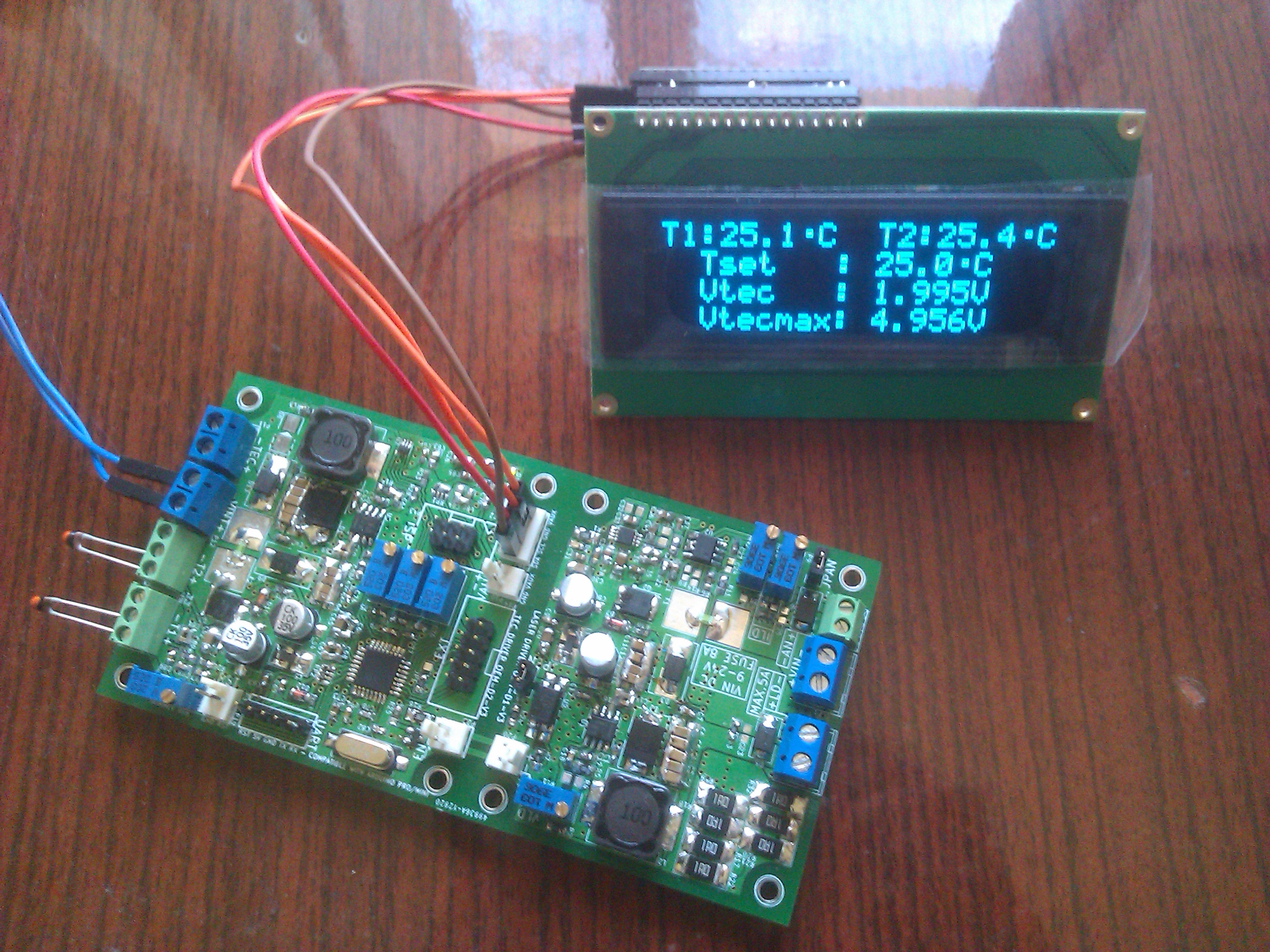
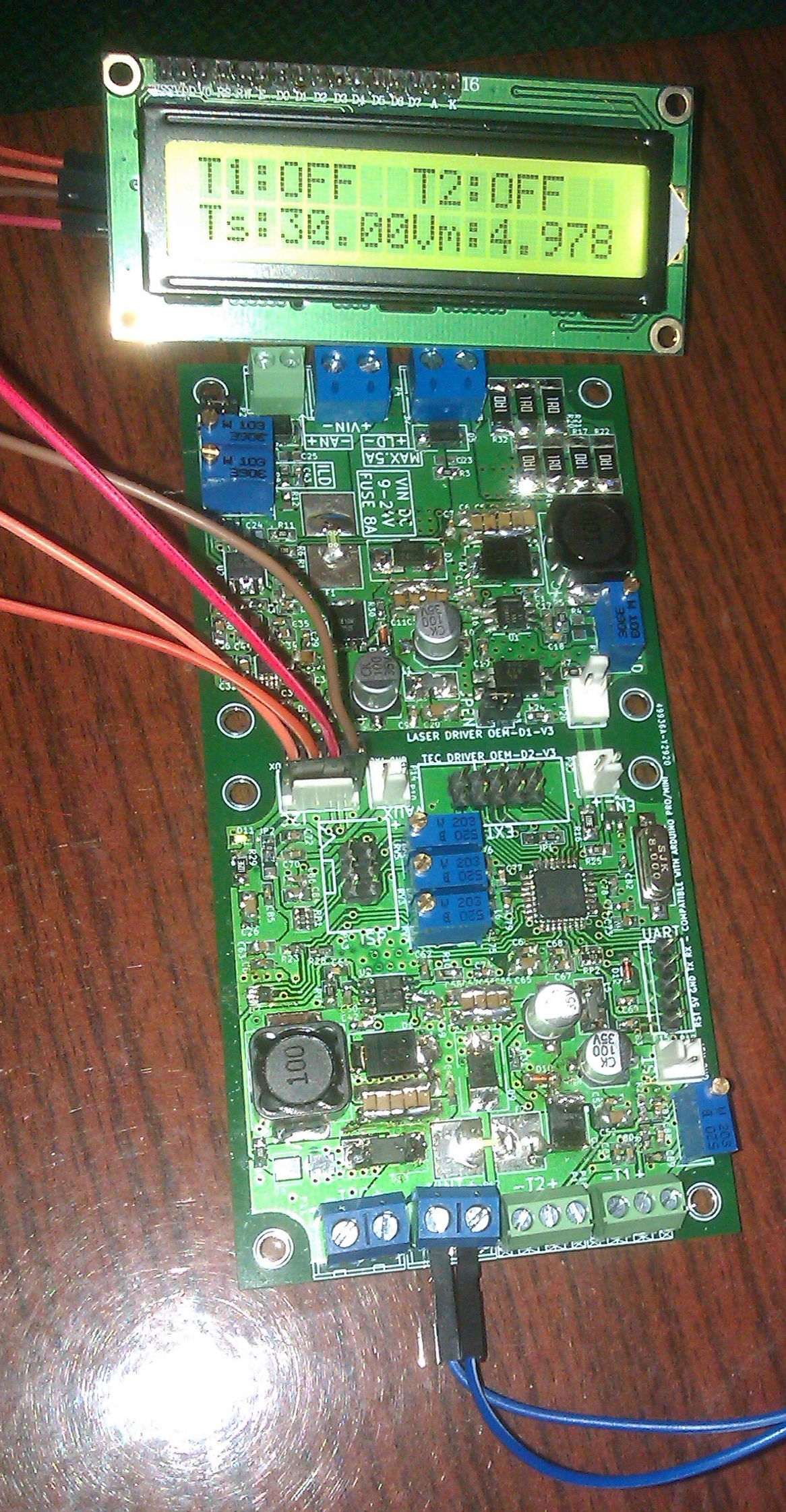
LCD Display
-
T1: Current Temperature of sensor 1.
-
T2: Current Temperature of sensor 2.
-
Tset: Target temperature. This is the maximum working temperature of the laser diode during normal conditions (set by trimmer RV6).
-
Vtec: Current voltage of the TEC element.
-
Vtecmax: Maximum voltage of the TEC element. (Set by trimmer RV7)
The board uses an OLED or LCD display of type 2004 or 1602. The display is connected via an I2C adapter. Changing the screen type requires a reprogramming of the microcontroller.
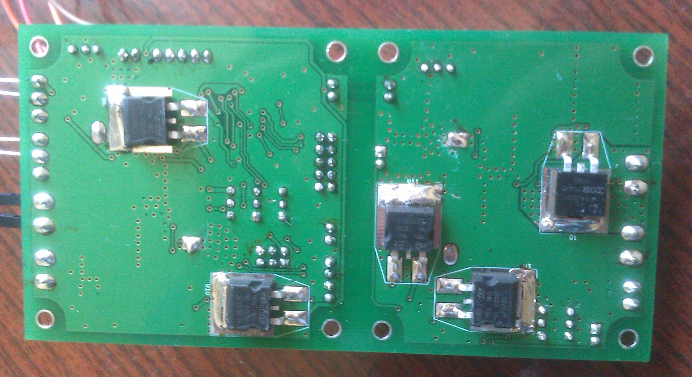
Cooling
A heatsink can be attached to the backside of the board if needed. Especially important for decreasing the overall board temperature is a suitable setting of the laser diode operating voltage by means of the trimmer VLD. The voltage VLD should be between one and two volts above the laser diode forward voltage.
If you wish to know more about the driver, please drop me a note using the about page.