ILDA Board
Posted by S. Ilchev on Sunday, 24 March 2019
This is the newest version of my ILDA board for use in multimedia laser systems.
1. Technical Data
- Compliant with the ILDA ISP99 standard specification.
- 4 color channels with analog modulation support: Intensity, Red, Green and Blue.
- X and Y scanner control with connectors for X- and Y- inversion.
- ESD protection on all ILDA inputs processed by the board.
- Opto-isolated Interlock and Shutter support.
- Three connectors for opto-isolated laser activation protection, e.g. for key lock, emergency stop button, etc.
- Isolated interlock and activation protection output for daisy-chaining of multiple lasers.
- Laser start delay, settable from 0 to 60 sec.
- Optional laser manual reset connector (protection against accidental laser activation in case of a power outage).
- Two sets of connectors for each color channel and each scanner dimension.
- Input and output ILDA connectors (respectively male and female DB25).
- Connector for optional MCU control.
- Shutter, interlock and status output connectors.
- Projector-on LED connector
- Power supply: dual power supply with -24V DC, GND and +24V DC connections.
- Fuses (1.5A-2A), reverse polarity protection, over-voltage protection.
2. Description
The main application of the board is in multimedia laser systems for animation projection. Such systems usually need an ILDA input and output ports, which are provided by this board. It is designed to receive, buffer, process and distribute the ILDA signals that control the laser system to other boards such as laser diode drivers and scanner drivers.
3. Setting up the board
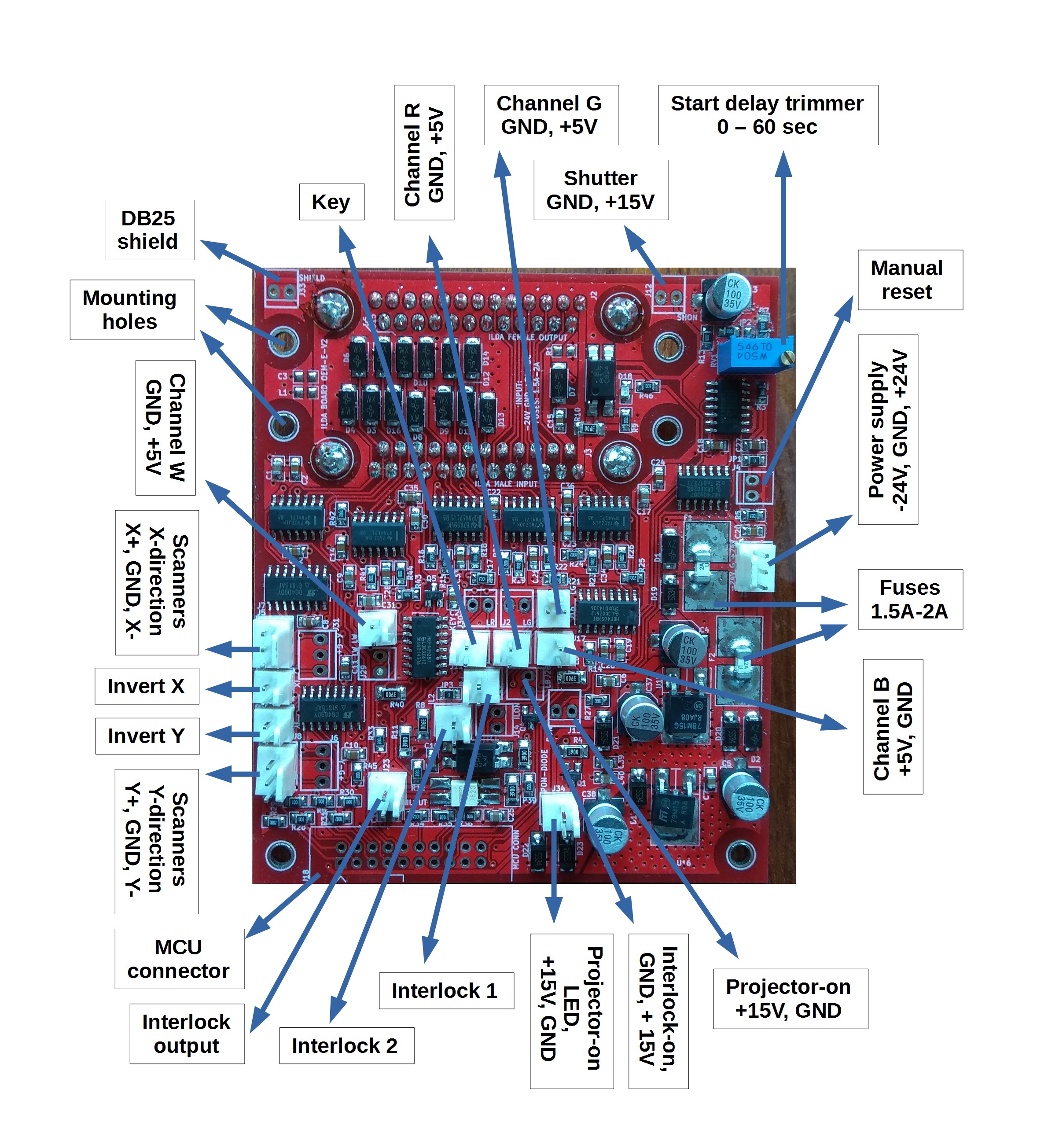
The board has multiple connectors, several solder jumpers and one trimmer for start delay adjustment. Their function is shown in the figure below.
- If “Interlock 2” will be used, please remove JP3 – if present.
- All connectors have a pin-to-pin distance equal to 2.54 mm.
- The range of the start delay trimmer is 0 – 60 sec.
- The “Invert X” and “Invert Y” connectors flip the projected animation in the corresponding dimension. They need SPST holding switches.
- The “Projector-on LED” connector is intended for a combination of a suitable resistor (between 1 kΩ and 2 kΩ) and an LED that shows when the laser projector emits light.
- The “Interlock-on”, “Projector-on” and “Shutter” connectors are binary outputs that indicate the corresponding status of the laser projector.
- The MCU connector is intended for a connection to a microcontroller and/or a scan-fail system that may take control over the animation projection.
- The “Channel W/R/G/B” connectors should be connected to the laser diode drivers
- The “Scanners X/Y-direction” connectors should be connected to the laser scanners.
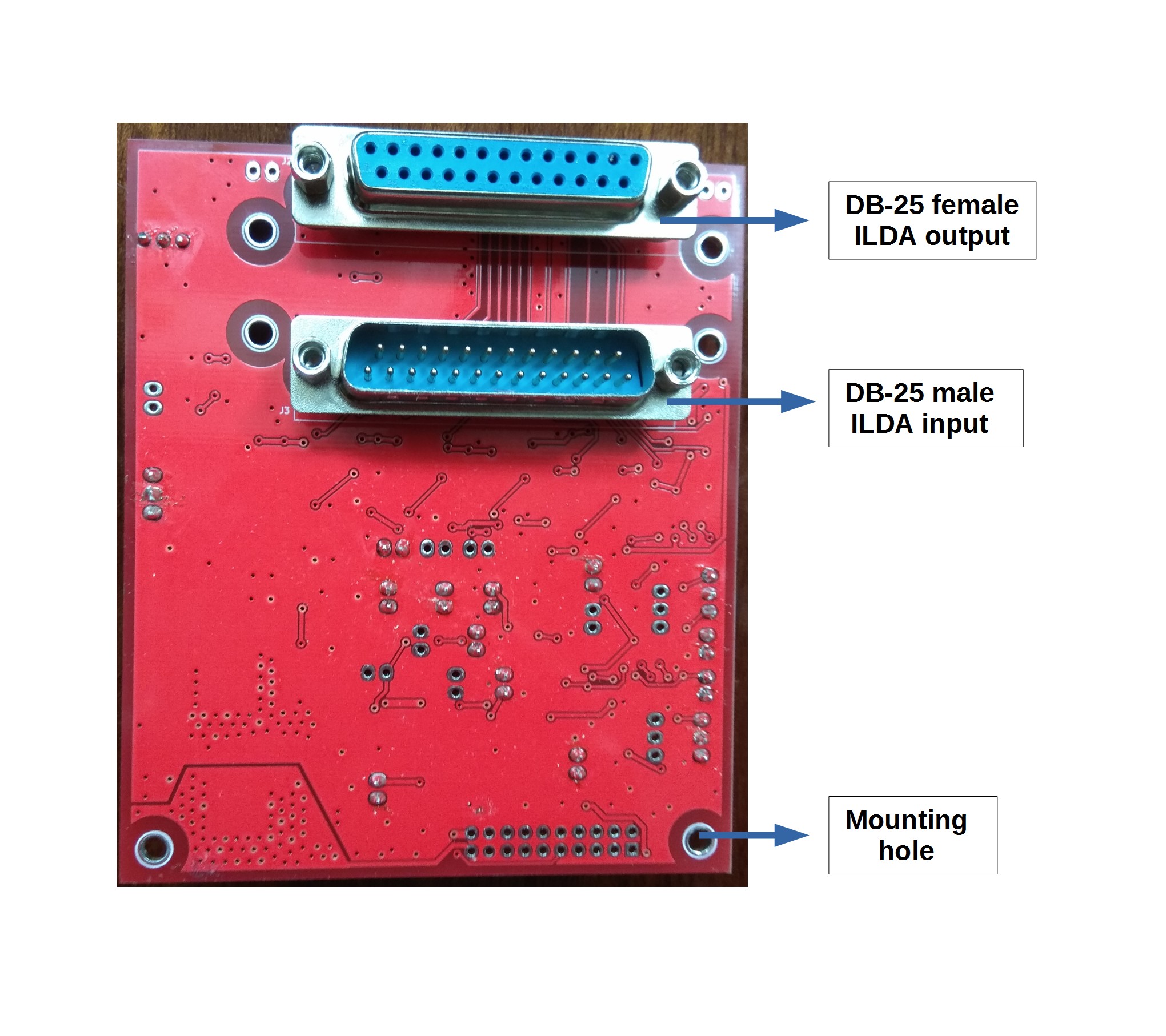
The back side of the board is shown in the figure below.
- The DB-25 male connector is the ILDA input connector.
- The DB-25 female connector is the ILDA output connector for daisy-chaining multiple lasers.
Link to the PDF datasheet: ![]() ILDA_V2_Datasheet.pdf
ILDA_V2_Datasheet.pdf